
Guide
How to design a 3D printed enclosure with AI
An AI agent can design a printable enclosure around your electronics in an afternoon: standoffs, connector cutouts, vents and a lid that screws on. The result is only as good as the information you give it, so most of the work is preparing the dimensions and checking the fit before the first print.
What to prepare
- The board. Outline, thickness, mounting holes and their spacing. A STEP model from the manufacturer is best: the agent can place the case around the real geometry, including connectors and tall parts.
- Everything else inside. Battery, display, buttons, sockets, cables. Size and where they go.
- What must be reachable. USB ports, SD card, buttons, LEDs, cable glands, and from which side.
- How it closes. Screws from below, heat-set inserts, a sliding lid or snap fits.
- Printer and material. Nozzle size, PLA, PETG or ASA, and how much clearance your printer needs for parts that fit into each other.
Step by step
The steps use SOMA with a coding agent such as Claude Code or Codex. The general approach is in how to use AI for CAD.
- Start a new model and your agent. If you have STEP files of the board or other parts, add them with Import. The agent finds them in the model folder.
- Describe the enclosure with the dimensions from your preparation, see the example below. Ask the agent to place the board and other parts as reference parts: they are shown in the model but not exported for printing.
- Check the first version from all sides. Is every connector reachable? Does the lid cover what it should? Point at problems by clicking a part or drawing on the view.
- Cut it open. A section through each connector shows whether the opening lines up and whether the board sits on its standoffs.
- Explode it. Pulling the parts apart shows the assembly order: can you put the board in, then the lid, then the screws?
- Check for printing. The agent analyzes overhangs and wall thickness with the values of the 3D printing skill, SOMA shows problem areas in color. Fix them before slicing.
- Export each printed part as 3MF or STL. Print a test piece of the tightest area first, for example just the wall with the connectors.
An example prompt
A two-part enclosure for a Raspberry Pi 5 with its active cooler, printed in PETG with a 0.4 mm nozzle. 2 mm walls, 0.4 mm clearance around the board. The board sits on four standoffs for M2.5 screws in its 58 × 49 mm hole pattern. Openings for all ports on the board edges and for the microSD card. Vents in the lid above the cooler. The lid is held by four M3 screws into heat-set inserts in the base. Use the board's STEP file in inputs as a reference part. Make wall thickness, clearance and lid height parameters.
Every sentence answers a question the agent would otherwise have to guess. Requirements that should stay, such as the material or the screw type, go into the model's notes file, which the agent reads every time.
Rules of thumb for FDM printing
You do not have to type these into every prompt. SOMA gives the agent skills: sets of instructions for a topic, such as 3D printing, CNC or tolerances, which the agent reads when the topic comes up. The 3D printing skill brings these default settings:
| Setting | Default | What it does |
|---|---|---|
| Material | PLA | PLA, PETG, ABS, ASA or TPU. The skill adjusts clearances and walls to it. |
| Nozzle and layer height | 0.4 mm, 0.2 mm | Walls are planned as multiples of the nozzle width. |
| Build volume | 220 × 220 × 250 mm | Larger parts are split, with pins or a lap joint. |
| Max. overhang without support | 45° | Steeper faces are avoided, or the agent says where support is needed. |
| Max. bridge without support | 10 mm | Longer flat ceilings get a different shape or support. |
| Minimum wall | 1.2 mm | More where the part carries load or holds screws. |
| Clearance per side for sliding fits | 0.3 mm | For lids and parts that slide or turn. PETG gets 0.1 mm more. |
There are three ways to adapt them to your printer:
- In the Skills panel in the sidebar: click 3D printing and change material, nozzle, build volume, overhang, bridge, wall or clearance. The values are saved with the model.
- In the chat: “my printer handles 55° overhangs” or “use 0.2 mm clearance”. What you tell the agent, or write in the model's notes file, takes precedence over the settings. The example prompt above does that with 2 mm walls and 0.4 mm clearance.
- In the skill itself: under Settings, Skills you can edit the text of a built-in skill or write your own, for example with the hole sizes of the heat-set inserts you buy.
Beyond the settings, the skill tells the agent rules like these:
- Printed holes come out 0.1 to 0.2 mm small, so screw holes are modeled 0.2 mm larger.
- No printed metric threads below M6: heat-set inserts (for M3 a 4.0 mm hole, makers differ) or self-tapping screws (2.5 mm hole).
- Screw bosses at least 2.5 times the hole diameter, joined to a wall or ribs.
- Horizontal holes get a pointed (teardrop) or flat top instead of sagging.
- Edges on the bed get a small chamfer instead of a fillet.
- No gap narrower than 0.5 mm, no pin thinner than 2 mm, letters at least 5 mm tall.
- The largest flat face goes on the bed, and loads run along the layers, not across them.
When the agent runs SOMA's printing check, it uses the same values: faces steeper than the overhang angle and walls thinner than the minimum show up in color. Values that come from your printer are worth one test print, for example a small lid and box to find the clearance that fits.
Check before you print
- Measure the distances that matter: board to wall, connector to opening, screw holes to their counterparts.
- Section through every connector and every screw.
- Explode the assembly and go through the order in which you put it together.
- Collisions: nothing should overlap in the closed state, especially tall parts on the board and the lid.
- Test print the critical part before the full enclosure. It costs minutes instead of hours.
Example: a sensor logger enclosure
This desk enclosure for a sensor logger with a 2.8″ touch display (ESP32-S3) was designed with an agent in SOMA, starting from an existing CadQuery project. It holds the display board, a battery, four GX12 sensor sockets and three small boards, and is 152 × 88 × 52 mm.
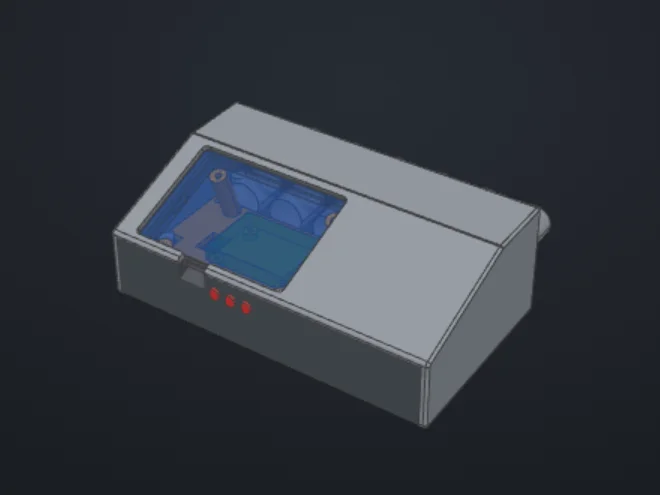
- Three printed parts plus three button plungers: a base with the battery and the sockets, a middle frame that carries the display board and the modules, and a cover.
- Printable without supports: each part was designed for its orientation on the bed. Ledges inside the base have 45° supports built into the design.
- Details that came from checking: a guide behind the SD card slot so the card cannot fall into the case, a recess to grip the card, and the USB-C port left free for charging.
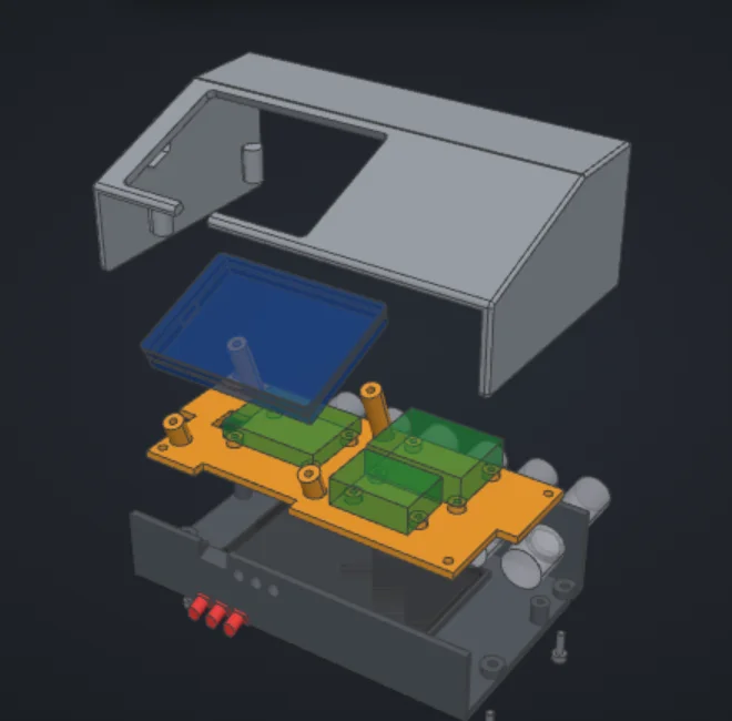
You can turn it, cut it open and explode it yourself on the models page.
Questions
Can AI design a case for my circuit board?
Yes. Give the agent the board size, hole pattern and the positions of the connectors, ideally as a STEP file of the board. It models the case around the board, with standoffs, cutouts and a lid. Check the connector cutouts and the fit before you print.
How do I get the connector positions right?
The best source is a STEP model of the board from the manufacturer, imported as a reference part. Without one, measure the board with calipers and give the agent the positions from one corner. Cut the model open at each connector to see if the opening lines up.
Which filament is best for electronics enclosures?
PLA is easy to print but gets soft above about 55 °C, which a closed case in the sun or next to warm electronics can reach. PETG or ASA hold up to more heat. Tell the agent the material: it affects wall thickness, clearances and how screws hold.
Can AI design snap-fit lids?
Yes, but snap fits depend heavily on the material and the printer. Screws or heat-set inserts are more forgiving for a first version. If you want a snap fit, ask for the hook as a parameter and print a test piece.
Should I export STL or 3MF?
Both work in common slicers. 3MF keeps units and several parts in one file, STL is supported everywhere. Export each printed part as its own file so you can orient and slice them separately.
Try it
SOMA is free and open source. Bring the agent you already use.